Fire Alarm Style Circuit
Introduction
For this project, I built a simple "fire alarm style" circuit that activates a flashing warning light and a pulsing buzzer when it gets triggered. The goal was to recreate that recognizable alarm pattern where the light and sound don't match perfectly, because in real alarms the visual and audio signals often run at different rates to grab attention better. To do that, I designed the circuit using two 555 timers so I could control the LED timing separately from the buzzer timing. I kept the whole system on a 5V supply so it would be safe, easy to test on a breadboard, and compatible with basic lab power sources.
Process
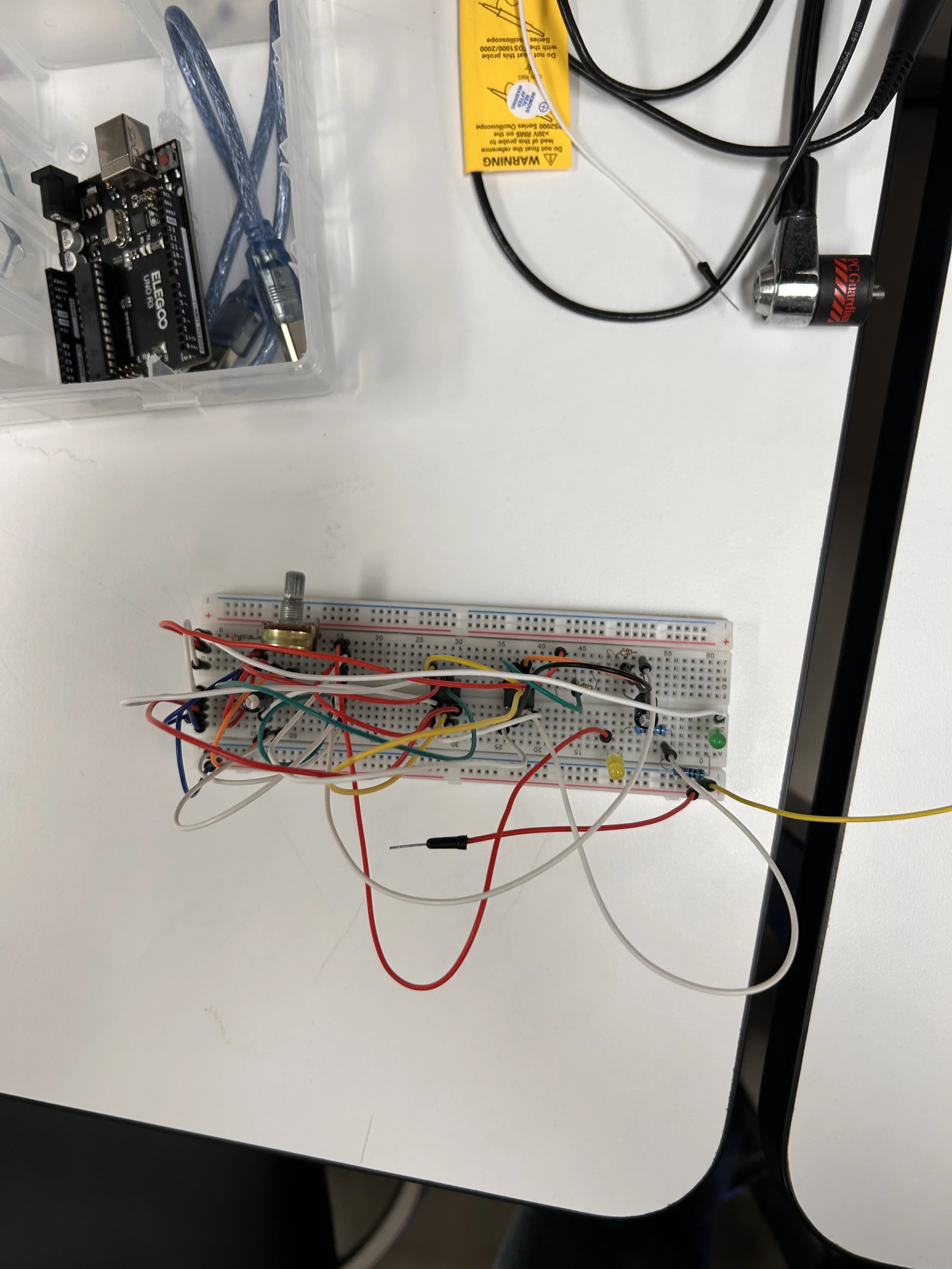
I started by planning the circuit as two independent timer sections that share the same trigger and power, but oscillate at different frequencies. Each 555 timer was set up in astable mode so it would continuously cycle on and off once the circuit was activated. One timer was dedicated to the LED flash rate, and the other controlled the pulsing rate for the sound. Before connecting the buzzer, I tested both outputs using LEDs so I could clearly see what the timing was doing and confirm that both timers were behaving correctly. That step helped a lot because it made debugging easier and let me adjust the timing without the buzzer adding confusion.
Once both timing patterns looked right, I replaced one of the test LEDs with the buzzer. Since the LED needed protection, I added a 1k resistor in series so the current stayed safe and consistent. I also paid attention to stability, because small wiring issues or loose connections can change the timing and make the pattern feel random. By keeping the power at 5V and making sure the components were placed cleanly, I was able to get a steady flash and pulse that stayed consistent through repeated tests. After that, I ran multiple trigger tests to make sure the circuit responded the same way each time and didn't drift or glitch.
Real World Impact / Conclusion
This kind of circuit connects directly to real alarm and warning systems, where the main purpose is to get someone's attention fast and clearly. Having both a visual signal (flashing LED) and an audio signal (pulsing buzzer) makes the system more effective, especially in environments where one signal might be missed. Using two different frequencies is also realistic because it creates a stronger "alarm feel" and helps prevent the pattern from blending into the background.
Overall, this project helped me understand how timing circuits work in a practical way, especially how the 555 timer can be used to create reliable output patterns. It also showed me the importance of testing in steps, like using LEDs first before switching to a buzzer, and how small design choices like resistor protection and stable wiring make the circuit work consistently.